MSI Modded BIOS Flash
Flashing unsigned firmware on MSI motherboards
Flashing an unsigned (modded) firmware image on an MSI board isn’t as simple as using M-Flash on your modified image. M-Flash does signature verification before flashing the image, and as a result, a different method must be used when the signature is changed.
Requirements
Requires at least one of the following:
- USB BIOS Flashback
- JTPM/JSPI header
Flash BIOS button
Disclaimer: Flashing modified firmware voids your warranty. Proceed at your own risk.
On every MSI motherboard I have used, the Flash BIOS button with USB flashing has allowed flashing of unsigned firmware. Consult the manual of your specific motherboard for exact steps for your model, but generally the steps are as follows:
- Format a USB drive as FAT32. I have had better luck with drives ≤ 8GB and USB 2.0.
- Obtain the firmware for your motherboard from https://www.msi.com/support/download.
- Complete any modifications you desire.
- Save desired firmware image as MSI.ROM on the root of your USB drive.
- Insert the USB into the Flash BIOS port, consult manual if it is not labeled on the board.
- Push Flash BIOS Button, LED will start to flash.
- Wait for LED to stop flashing.
SPI Flash
Disclaimer: Attaching an SPI programmer voids your warranty. Proceed at your own risk.
The SPI Flash is where the actual firmware resides, and it can usually be flashed directly by using a programming clip or attaching directly to the SPI bus using the TPM2 header. On some MSI motherboards, the TPM2 header shares the SPI bus with the SPI flash chip.
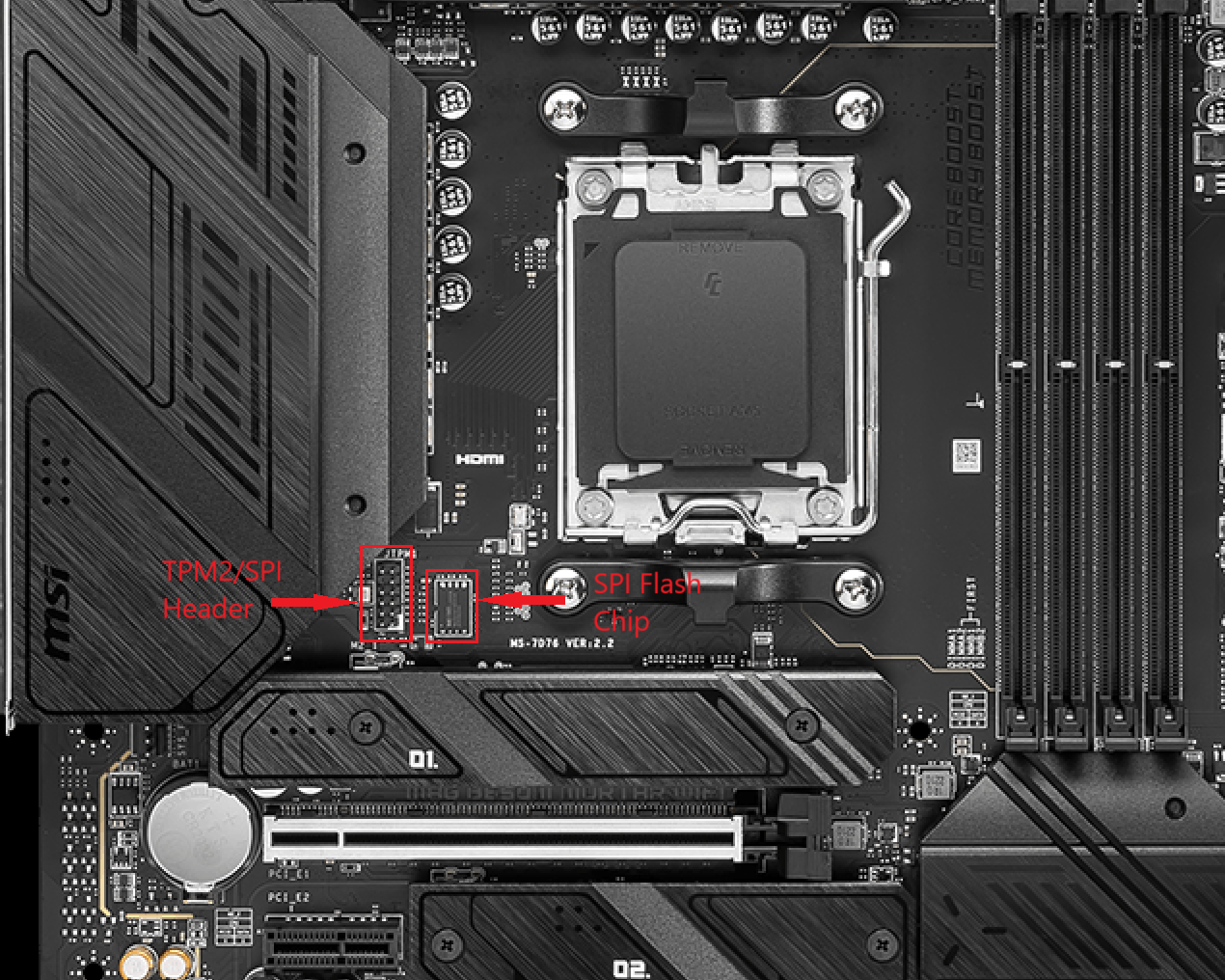
To determine if the SPI bus is shared, you can use a multimeter to continuity test between the pins of the TPM header and the SPI flash chip. If the bus is shared, you can probably assume the pinout is the same as the from the flashrom documentation (see below), but you should verify this before connecting. To determine the voltage you can safely use for the chip, consult the datasheet for the model number silkscreened on the chip. 1.8V is more common for recent AMD Ryzen boards. Using an unmodified CH341A USB SPI flash adapter (which are 5V by default) will almost certainly fry a 1.8V chip. Use an adapter or better yet, a CH347F based flasher that has 1.8V output.
Description
| name | function |
|---|---|
| VCC | Voltage (See flash chip datasheet) |
| MISO | SPI Master In/Slave Out |
| MOSI | SPI Master Out/Slave In |
| #SS | SPI Slave (Chip) Select (active low) |
| SCLK | SPI Clock |
| GND | ground/common |
| #HOLD | SPI hold (active low) |
| #WP | SPI write-protect (active low) |
| NC (NP) | Not Connected (or No Pin) |
JSPI1 (6×2)
| name | pin | pin | name |
|---|---|---|---|
| VCC | 1 | 2 | VCC |
| SO | 3 | 4 | SI |
| #SS | 5 | 6 | CLK |
| GND | 7 | 8 | GND |
| NC | 9 | 10 | NP |
| #WP | 11 | 12 | #HOLD |
JSPI1 (5×2)
| name | pin | pin | name |
|---|---|---|---|
| VCC | 1 | 2 | VCC |
| MISO | 3 | 4 | MOSI |
| #SS | 5 | 6 | SCLK |
| GND | 7 | 8 | GND |
| #HOLD | 9 | 10 | NC |